skip to main |
skip to sidebar
A few days ago I received a package in the mail from Archive Sound. Inside the small parcel I found a plastic baggie filled with small slimy rubber bits. Just what I had been waiting for. These were, of course, the new bushings for the Minimoog's keyboard.
Minimoogs, like several other vintage synths, have keyboards made by a company called Pratt-Read. Apparently P-R stopped making synth keyboards many years ago, and now they make screwdrivers. I can't really find any info about P-R keyboards, their history in the keyboard-making business, or what made them give it all up for screwdrivers. Perhaps we'll never know. I'm waiting for the shocking tell-all novel, or at least a Wikipedia entry.
The bushings are the small rubber bits that fit snugly inside the individual keys, and as far as I can tell, their purpose is to give the keyboard a nice soft (almost squishy) action. Since these keyboards are so old now (mine's 34 years old), the rubber bushings become hard, and they sometimes even disintegrate. With old bushings, keys become uneven, and they have a harder action. Sometimes they click.
Installing the new bushings is a pretty simple job. If you get your replacement bushings from Archive Sound, they have instructions on their web site. I'll try not to be redundant here.
 Removing the keyboard from the Minimoog is fairly simple. On the bottom of the synth are a bunch of wood screws keeping the bottom panel in place. The bottom of my synth has a little something extra, as you can see in the picture (Backbone lives!).
Once you remove the bottom panel you can see the keyboard assembly much clearer, and the screws holding it in place. The keyboard is connected via a cinch connector, which needs to be disconnected. MAKE SURE you mark the connector so that you can put it back together the right way. The keyboard is screwed into the case through some wooden shims that keep it at the right height. There are four of these shims (although I understand that some later versions don't have them). If the shims aren't glued in place, make sure you know which one goes where, as they are different heights. After the keyboard is unplugged and unscrewed it should just come out.
 Since the bushing replacement required the removal of the plastic key covers I took that opportunity to clean them. The whole keyboard assembly was really gross, actually, so I gave it a thorough dusting and I washed the keys in soapy water. Super-duster spray and Q-tips took care of the rest.
 The bushings are the white bits with pointy ears visible inside the keys in the above picture. They are kind of awkwardly placed, so you need a tool well-suited to remove them. I found that a flat-head precision screwdriver (the kind used in computer repair) worked perfectly. You just need to jam the screwdriver under the bushing, work it a little bit, and pull it off. Some bushings don't come out in one piece, so the screwdriver also comes in handy for scraping remnants off of the key.
Once the old bushings are off, just pop the new ones on and you're set. Make sure you get the bushing right-side up. The bottom and the top look similar but they're not the same.
The keys on the synth feel a lot nicer now. The Pratt-Read bushing kit is a good buy if you want to bring some life back in to your old synth keyboard.
I'm very excited about this one. This is a mod that I had secretly been thinking about for quite a while, but I made no mention of it for fear that it wouldn't end up happening and I'd have to eat my words. Fortunately none of that happened, and I ended up being able to do the mod. Namely, I have added illuminated pitch and mod wheels to the synth.
This is something that I've seen before on the newer Minimoog "Voyager" synths, which are currently being made by Moog Music. It did cross my mind that this mod might detract a bit from the "classic" appeal of the synth, but I also knew that the very last run of the original Minimoogs had illuminated wheels, so it wasn't altogether sacrilegious. And anyway, screw all that - it looks freaking awesome.
The mod itself was quite simple, but it depended on a couple of key things happening. First, I had to find clear plastic wheels for the minimoog (my original ones were opaque white plastic), and secondly I had to figure out a way to draw power to the LEDs without messing up the synth. Synthesizers like this one depend on precise voltages to make it work, and I didn't want to mess with that without some advice from people who have done it before.
The first thing I did was to call Moog headquarters in North Carolina. I just like hearing their accents. Their tech department is quite helpful even when talking about a synth they haven't produced in 25 years. The guy I talked to explained it pretty simply: "Basically you need a clear wheel, and you point an LED at it." He pretty much blew my mind.
Next, I looked up "plastics manufacturing" in Google and found one in the Vancouver area. I dropped in to talk to a fabricator, and brought one of the original white wheels with me. I asked if he could make two of these for me in clear plastic, and he said no problem. They cost me about $20 a piece, which was more or less what I expected. In two days they were done and they looked amazing. I installed them in the Moog's left-hand control as soon as I got home.
 The wheels are a fairly simple mechanism. Basically they have a quarter-inch hole in their center, which fits snugly on the end of a potentiometer. Inside the wheel is a little black hex screw to secure it to the pot. If you're doing this mod and you're talking to a plastics manufacturer, make sure the hole for the screw is done properly, including the threading for the screw itself.
The pitch wheel has an extra mechanism to make it lock in to its center position (called a "detent") - essentially there's a small pointy plastic cone that pushes against the wheel and when the wheel is in its center position the cone locks in to a small dimple in the wheel itself. Again, if you're dealing with plastics people, the dimple in the wheel is pretty important, and could be easily missed.
Once the wheels were in place I had to figure out how the heck to get LEDs running underneath them. I tried posing this question to a Minimoog forum but I made the mistake of mentioning that I was "fairly new to the world of electronics" (I said this in hopes of getting some gems of knowledge from them), instead all I got back was people telling me that "pulling apart a vintage synthesizer" was not the place for one to make their debut in electronics. The only thing I learned from them was that people won't help me if I say I'm fairly new. I think they assumed I meant I was a beginner, which isn't the case. My skill is more at the "intermediate" level. Besides, they were overstating the difficulty of the project: there's very little pulling apart of anything involved in the job, unless you count loosening screws (hardly an advanced task).
I then sent an e-mail to a professional synth tech. I knew he's probably done this mod a million times before, so I was hoping he'd give me some tips. Luckily for me, he responded very quickly, and even sent me some photos of projects he's done to give me some ideas. He gave suggestions on choosing LEDs, placement of LEDs, how to mount them, and where to draw power for them. With his advice, in combination with the detailed documentation available at FantasyJackPalance.com I had all the information I needed to begin the work.
 Powering LEDs is a pretty simple task, but I still didn't want to risk messing up the synth, so I did all my planning on a breadboard. The Minimoog has +10v available inside the left-hand control area, so I mimicked that by generating 10 volts with a small project power supply that I built a while back. It lit up like glory, as you can see in this picture.
The next step was to figure out a method of mounting the LEDs inside the Minimoog. Unfortunately I wasn't able to find the same type of terminal strip that was suggested to me, but it did give me ideas on how to improvise. I got a hold of a small pliable metal bracket, which seemed perfect for the job. I mounted the bracket on the outer screw for the decay switch, right above the wheels.  Small standoffs would have been perfect for the job, but I couldn't find any, so I swapped the screw for an extra long one (3/4"), and fastened the bracket with some nuts. You can see what I'm talking about in the picture to the left. I had to do a little drilling on the bracket to get it to fit over the screws but that was simple enough.
Next, I took my little LED circuit and made it permanent on a small solder strip. The plan was to attach the whole thing to the top of the bracket, so I drilled a hole for a screw in the strip. If you're going to do something like this, make sure you design it so the screw and the bracket are safely distanced from the components of your circuit. You don't want to inadvertently short it.
 Once the LED circuit was assembled I mounted it on to the bracket. I had it positioned so that it spanned the two wheels, with an LED on each end. I kept the LED leads nice and long so I'd be able to place them so they almost touched the wheels.
By the way, clicking on any of these photos will take you to a larger version, or you can see a whole set of them on Flickr.
Power for the LED circuit was drawn from the +10v terminal on the cinch connector at the top of the left-hand control area. If you're looking at the connector like this, the +10v is one pin below the top-left. Make sure you consult documentation and test the pin with a multimeter before you use it. Ground is just to the right of the +10v pin, and it's distributed all over the left-hand control area. I connected to the +10v right at the connector, and I grounded the circuit using the ground connection on the pitch bend potentiometer.
And that, my friends, is all it took. It was a lot of finnicky work but relatively simple. It really paid off in the end:

With the taste of success still on my lips (or was it lacquer thinner?) I decided the next step in the Minimoog restoration would be a bit bolder. The Minimoog and I had reached a special stage in our relationship; I was one of the few lucky guys to have had a peek under her hood, so to speak. Now I wasn't so afraid to turn her around, brandish my tool, and poke around inside of her. And eventually I got around to doing some repairs as well (nyuk, nyuk).
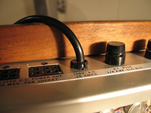
So I set my sights on one of the other minor issues I wanted to fix: the power cord. Obviously Backbone is a band that rocked pretty hard on stage, and nowhere was it more evident than the Minimoog's tattered power cord.
As you can see, the cord was torn and taped up right were it goes in to the synth. Also Backbone managed to rock so hard, the ground prong came right out of the plug. That's just the awesome effect of Backbone. And sure, the synth worked just fine with the cord like that. It could have even been an advantage to not have a ground prong on the plug - what if Backbone was rocking a stadium that only had two-prong outlets? But I just couldn't bear it. It felt like the cord was neutered at one end and just broken at the other end. So this was my next project.
Inside the synth, the power supply to the electronics is all on the left hand side, near where the power cord comes out. A couple of circuit boards block a clear view of the wiring, but fortunately the boards are connected via sockets, and easily removed. It looked like this:
 The power cord has three wires: black, white and green. The black wire (the "hot" wire) is connected to the bottom of a fuse holder on the right. The fuse holder is connected to a brown wire, which leads to the transformer (the silver box on the left). The white ("neutral") wire is connected to part of the power switch. The green wire (the ground) leads to one of the screws that hold the transformer in place. I made sure I didn't get any of that mixed up. I didn't want to fry the synth.
I used a 10' computer power cord (I had to lop off the female end) to replace the original one. The operation was actually pretty simple, and it afforded me the opportunity to use my soldering iron, which I haven't touched in a while. I love the smell of melted solder rosin. The above picture is of the completed operation, from the inside. Here's the outside:
 Probably the biggest challenge (which I realize now is really simple) was figuring out how the strain relief came out. That's the black plastic bit that wraps around the cord as it comes out of the synth. In the end it just needed some perseverance with needle-nose pliers, squeezing from underneath. As you can see, the new cord fit snugly into the strain relief, and eventually it all got put into place.
As I mentioned before, my Minimoog has a few aesthetic issues that I plan to work on. Generally it looks good. The keyboard is in relatively good condition, the controls work well save for a couple of pots that make noise... You can tell it wasn't made yesterday, but you can also tell that it's been handled well over the years. If it was in bad shape I wouldn't have bought it.
The most glaring of the cosmetic issues on the synth could only be seen from the back:
 Apparently the original owner of the Minimoog was in a band called "Backbone". Evidently this individual decided that the best way to advertise the band's name was to spray paint a logo on the back panel of the synth. As you can see, it looks AWESOME. I can just imagine how excited the other members of Backbone must have been when they saw their badass logo on the Minimoog.
"Dude, that looks killer. You can't even tell that it's a home job - that's how pro it looks."
"Yeah, people are going to be asking how we managed to get Moog to make us a custom synth with our logo on it! How did you do that anyway? It's TWO colors!"
"Easy. I just used a stencil, and sprayed red on the bottom and yellow on the top. I got a little bit of red outside the stencil on the right, but no one will see that."
"It looks like the letters are coming out of a glorious sunset, reminding us of the glory of Backbone."
...and so on. Actually it did have a little humour value, but that faded quickly enough and I just wanted to get rid of the logo. It's also sprayed on to the bottom of the synth, but NO ONE sees that, and I'm going to replace the wood eventually anyway. So after I did a quick Google search to make sure Backbone wasn't some famous old rock band (I had visions of auctioning it off to a wealthy Backbone fan for thousands of dollars), I set out to remove the ugliness.
The first step was to remove the back panel. It's held on by about a dozen screws, and it was fairly easy to do. It gave me an opportunity to have a peek inside the Minimoog:
 Clicking on the image will bring you to a bunch more shots. Here you can see the osc board. That's about as technical as I get with these things, is being able to identify this particular board.
Having removed the back panel, I removed the four machine screws designed to keep the Moog in its "upright" position, and I wiped off all the dust and grime. I had a few solvents that I was going to try for the job of removing the paint.
Before I began wiping chemicals all over the outer panel of the mini, I thought it might be a good idea to test them out by applying them in small hidden areas on the inside of the panel. I didn't want to end up with some chemical reaction that ruined the panel altogether. Fortunately there was nothing to worry about, and lacquer thinner turned out to be the solvent of choice.
 Using the "clean rag" method, I put solvent on a small clean area of my rag, and started wiping up the paint, which basically melted under the lacquer thinner. I worked on it a little bit at a time, using a clean part of the rag with each pass. It was more time consuming this way, but it made very little mess and the paint was cleaned off quite well.
I thought it would be prudent to use gloves while handling such potent chemicals, so I wore a pair made of polyurethane. They lasted about a minute before they started to melt. I guess lacquer thinner and poly gloves don't mix. Well, actually they do mix and that's the problem, if you want to get technical. Another thing I learned is that kitchen sponges which have a green scrubby material on one side shouldn't be used with solvents. Turns out the scrubby material is made of some kind of plastic that dissolves rather quickly. Also, water doesn't rinse lacquer thinner out of a rag. And don't sniff the rag to see if it still has lacquer thinner on it. Seriously.
The panel also had tiny areas that looked like rust, and I managed to get that off with a little CLR cleaner (which I also spot tested on the inside of the panel).
In the end the panel is nice and clean. If you look at it under bright light at a certain angle you can still see the shape of the Backbone logo. I tried scrubbing it out with steel wool, and it just wouldn't disappear. If anyone knows what might do the trick be sure to let me know. It's hardly noticeable though, and I'm quite happy with the result. Here it is:

Welcome to the repository for all of my synth-related projects. If you love electronic musical instruments like I do, I hope you will appreciate the contents of this blog. I must warn you of two things: first, it's going to get very geeky. Second, I know VERY little about electronics, so I am kind of flying by the seat of my pants here. If you're here looking for knowledge you may find it in the "resources" section on the right, or perhaps in the comments if anyone happens to say anything enlightening (or indeed anything at all). I'm not going to pretend to be an expert about anything electronics-related, and hopefully this will be a learning process for me.
Allow me to introduce you to a good friend of mine:

This is, of course, a Minimoog synthesizer, model D, made in 1973 by Moog Music Inc. If you've never heard of it you'd better ask somebody.
I purchased this synth about six months ago, and it sounds amazing. It's got the "original" oscillator board (later Minimoogs have a re-designed osc board to improve tuning stability; some folks say they don't quite have the character of the original synths). Work has been done on the synth to fix tuning issues, and it seems to be fine in that department. It sounds warm and, pardon the cliché, fat.
There are a few minor aesthetic issues with the synth though (but come on - it's 34 years old!), and that is the subject of the first series of posts I will be making to this blog. I will be cleaning it up, doing some minor part replacement, restoring the keyboard, and hopefully giving it a brand new custom-made wood casing.