
This is something that I've seen before on the newer Minimoog "Voyager" synths, which are currently being made by Moog Music. It did cross my mind that this mod might detract a bit from the "classic" appeal of the synth, but I also knew that the very last run of the original Minimoogs had illuminated wheels, so it wasn't altogether sacrilegious. And anyway, screw all that - it looks freaking awesome.
The mod itself was quite simple, but it depended on a couple of key things happening. First, I had to find clear plastic wheels for the minimoog (my original ones were opaque white plastic), and secondly I had to figure out a way to draw power to the LEDs without messing up the synth. Synthesizers like this one depend on precise voltages to make it work, and I didn't want to mess with that without some advice from people who have done it before.
The first thing I did was to call Moog headquarters in North Carolina. I just like hearing their accents. Their tech department is quite helpful even when talking about a synth they haven't produced in 25 years. The guy I talked to explained it pretty simply: "Basically you need a clear wheel, and you point an LED at it." He pretty much blew my mind.
Next, I looked up "plastics manufacturing" in Google and found one in the Vancouver area. I dropped in to talk to a fabricator, and brought one of the original white wheels with me. I asked if he could make two of these for me in clear plastic, and he said no problem. They cost me about $20 a piece, which was more or less what I expected. In two days they were done and they looked amazing. I installed them in the Moog's left-hand control as soon as I got home.
 The wheels are a fairly simple mechanism. Basically they have a quarter-inch hole in their center, which fits snugly on the end of a potentiometer. Inside the wheel is a little black hex screw to secure it to the pot. If you're doing this mod and you're talking to a plastics manufacturer, make sure the hole for the screw is done properly, including the threading for the screw itself.
The pitch wheel has an extra mechanism to make it lock in to its center position (called a "detent") - essentially there's a small pointy plastic cone that pushes against the wheel and when the wheel is in its center position the cone locks in to a small dimple in the wheel itself. Again, if you're dealing with plastics people, the dimple in the wheel is pretty important, and could be easily missed.
Once the wheels were in place I had to figure out how the heck to get LEDs running underneath them. I tried posing this question to a Minimoog forum but I made the mistake of mentioning that I was "fairly new to the world of electronics" (I said this in hopes of getting some gems of knowledge from them), instead all I got back was people telling me that "pulling apart a vintage synthesizer" was not the place for one to make their debut in electronics. The only thing I learned from them was that people won't help me if I say I'm fairly new. I think they assumed I meant I was a beginner, which isn't the case. My skill is more at the "intermediate" level. Besides, they were overstating the difficulty of the project: there's very little pulling apart of anything involved in the job, unless you count loosening screws (hardly an advanced task).
I then sent an e-mail to a professional synth tech. I knew he's probably done this mod a million times before, so I was hoping he'd give me some tips. Luckily for me, he responded very quickly, and even sent me some photos of projects he's done to give me some ideas. He gave suggestions on choosing LEDs, placement of LEDs, how to mount them, and where to draw power for them. With his advice, in combination with the detailed documentation available at FantasyJackPalance.com I had all the information I needed to begin the work.
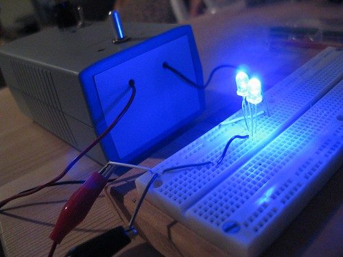 Powering LEDs is a pretty simple task, but I still didn't want to risk messing up the synth, so I did all my planning on a breadboard. The Minimoog has +10v available inside the left-hand control area, so I mimicked that by generating 10 volts with a small project power supply that I built a while back. It lit up like glory, as you can see in this picture.
The next step was to figure out a method of mounting the LEDs inside the Minimoog. Unfortunately I wasn't able to find the same type of terminal strip that was suggested to me, but it did give me ideas on how to improvise. I got a hold of a small pliable metal bracket, which seemed perfect for the job. I mounted the bracket on the outer screw for the decay switch, right above the wheels.
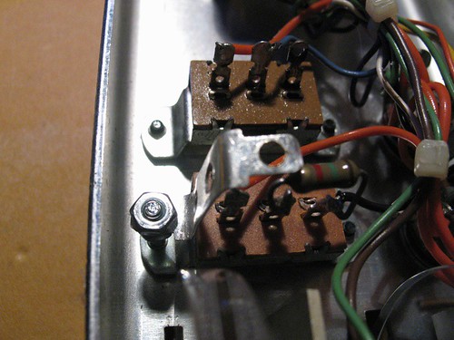 Small standoffs would have been perfect for the job, but I couldn't find any, so I swapped the screw for an extra long one (3/4"), and fastened the bracket with some nuts. You can see what I'm talking about in the picture to the left. I had to do a little drilling on the bracket to get it to fit over the screws but that was simple enough.
Next, I took my little LED circuit and made it permanent on a small solder strip. The plan was to attach the whole thing to the top of the bracket, so I drilled a hole for a screw in the strip. If you're going to do something like this, make sure you design it so the screw and the bracket are safely distanced from the components of your circuit. You don't want to inadvertently short it.
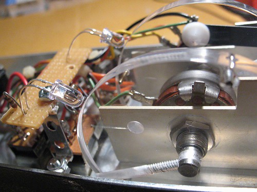 Once the LED circuit was assembled I mounted it on to the bracket. I had it positioned so that it spanned the two wheels, with an LED on each end. I kept the LED leads nice and long so I'd be able to place them so they almost touched the wheels.
By the way, clicking on any of these photos will take you to a larger version, or you can see a whole set of them on Flickr.
Power for the LED circuit was drawn from the +10v terminal on the cinch connector at the top of the left-hand control area. If you're looking at the connector like this, the +10v is one pin below the top-left. Make sure you consult documentation and test the pin with a multimeter before you use it. Ground is just to the right of the +10v pin, and it's distributed all over the left-hand control area. I connected to the +10v right at the connector, and I grounded the circuit using the ground connection on the pitch bend potentiometer.
And that, my friends, is all it took. It was a lot of finnicky work but relatively simple. It really paid off in the end:

2 comments:
I too tried to get help at the Moog forum but got no response. I had much better luck at, of all places, a Mini Cooper messge board. There was a guy there who is into electronics and he actually looked up the schematic and gave me some tips on where to go to solve the problem I was haiving.
Long story short - my Mini Moog is up and running no thanks to the people at the Moog forum who seemed rather clique-ish and unwilling to help a noob.
Good to hear! I would also recommend a Yahoo group called "Lords of the Mini". You have to apply to join the group, but they're a friendly bunch who love talking about Minimoogs. You'll find lots of useful stuff just by searching through past threads too.
Here's the link.
Post a Comment